 Started building a new magbot pendulum after
my attempt to make a magbot spinner failed.
Parts that will be used for the stand:
-wooden base (from an old amplifier)
-copper pipe
-brass fittings
Parts used for the electronic circuit:
-coil(from a VCR)
-3300 uF and 1000uF cap
-100K resistors
-pn2222n and 2n3906 transistor
-red LED
-4100 type diode
-solar cell
Step 1:
I built the circuit according to the picture(a very good
description
in the junkbots book,so no need for me to repeat that here).
Normally I would test it first on the breadboard but in this
case I took
the chance that it would work,and it did.The coil was
not soldered on yet.
Step 2:
I started soldering the pieces of copper pipe and brass
fittings together
to form the stand.
Step 3:
I Prepared the wooden base for the copper pipe.There was
already one hole
in the piece of wood but this was too big for the 12 mm pipe
so I had to use a brass socket.Then I drilled the other hole
with a flat
wood bit.Between these holes I drilled a 22mm,shallower,hole
for the coil to fit in so it is flush with the
surface of the wood.I then
drilled two small holes inside this hole for the ends
of the coil to go through(these will run on the underside of
the base to the rest of the circuit which will be housed inside an alumin(i)um box.
Started building a new magbot pendulum after
my attempt to make a magbot spinner failed.
Parts that will be used for the stand:
-wooden base (from an old amplifier)
-copper pipe
-brass fittings
Parts used for the electronic circuit:
-coil(from a VCR)
-3300 uF and 1000uF cap
-100K resistors
-pn2222n and 2n3906 transistor
-red LED
-4100 type diode
-solar cell
Step 1:
I built the circuit according to the picture(a very good
description
in the junkbots book,so no need for me to repeat that here).
Normally I would test it first on the breadboard but in this
case I took
the chance that it would work,and it did.The coil was
not soldered on yet.
Step 2:
I started soldering the pieces of copper pipe and brass
fittings together
to form the stand.
Step 3:
I Prepared the wooden base for the copper pipe.There was
already one hole
in the piece of wood but this was too big for the 12 mm pipe
so I had to use a brass socket.Then I drilled the other hole
with a flat
wood bit.Between these holes I drilled a 22mm,shallower,hole
for the coil to fit in so it is flush with the
surface of the wood.I then
drilled two small holes inside this hole for the ends
of the coil to go through(these will run on the underside of
the base to the rest of the circuit which will be housed inside an alumin(i)um box.
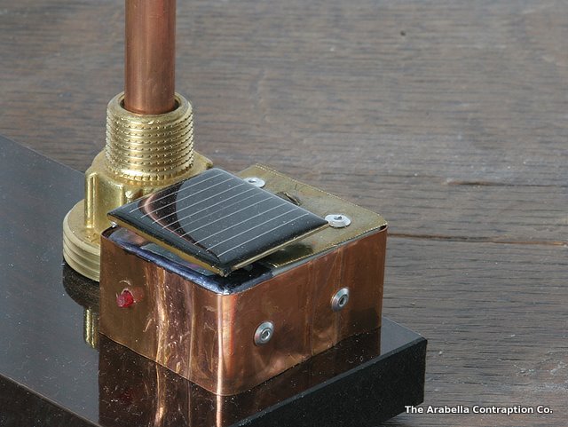
 Step 4:
The electronic circuit is housed in an
aluminium case out of an old radio.
I riveted a piece of copper and brass
sheet metal on this to keep the co-bra
theme going.A hole was drilled
for the LED to go through,then the solar
cell glued on top.A big brass screw
was then used to fix the housing on the
stand.
Step 4:
The electronic circuit is housed in an
aluminium case out of an old radio.
I riveted a piece of copper and brass
sheet metal on this to keep the co-bra
theme going.A hole was drilled
for the LED to go through,then the solar
cell glued on top.A big brass screw
was then used to fix the housing on the
stand.
 Step5:
The pendulum was made from a piece of metal
wire
out of an old radio and two brass parts,
super glued together.
Step5:
The pendulum was made from a piece of metal
wire
out of an old radio and two brass parts,
super glued together.
Home